NEW: Onshore Inspections
The Flux
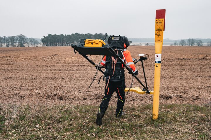
A robust handheld system for corrosion detection and 3D mapping of unpiggable pipelines.
Discover the Flux
Inspect The Unpiggable
NEW: Onshore Inspections
A robust handheld system for corrosion detection and 3D mapping of unpiggable pipelines.
Discover the Flux
NEW Service
Know how fast every coating defect corrodes, in µm/year, validated against excavations.
See how it works
FREE: Whitepaper
How CMI separates protected steel from actively corroding steel, without excavation.
Download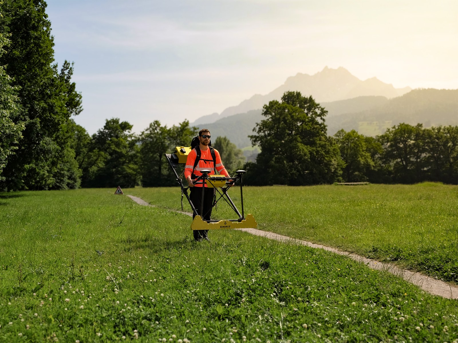
Bending strain shows what ground movement has done to a buried pipeline. In-line inspection measures it with an inertial measurement unit (IMU), but only where a pig can run. EMPIT’s Current Magnetometry Inspection (CMI) measures bending strain on unpiggable pipelines from above ground, and published comparisons show that it matches IMU data.
| Method | What it delivers | On unpiggable lines |
|---|---|---|
| ILI with IMU | Bending strain along the whole segment, change from run to run | No |
| Strain gauges | Strain change at single points, close to real time | Yes, but only where the pipe is exposed, and only the change since installation |
| Conventional line locator | Rough pipe position | Yes, but small deflections and deflections over long distances are not resolved |
| Passive magnetometry (LSM) | Zones of elevated mechanical stress | Yes, as a screening |
| CMI from above ground | Horizontal and vertical bending strain along the whole segment, repeatable | Yes |
Landslides rupture more pipelines than any other geohazard. In the PHMSA significant incident database, 23 incidents were caused by landslide movement between 1986 and 1995. Between 2010 and 2019 there were 22. Thirty years of better steel, better coatings and better inspection tools have not moved that number.
Newer data shows the same picture. From 2002 to mid-2022, landslides caused 43 pipeline ruptures in the United States, more than any other geohazard. In Europe, ground movement was behind 48% of rupture-sized incidents on gas transmission pipelines between 2010 and 2019, the largest single cause.
When ground moves, it drags the buried pipe sideways or downward. The pipeline moves and bends. The outside of the bend is stretched, the inside is compressed. Bending strain is that stretch, in percent.
It follows directly from the geometry: bending strain = pipe diameter / (2 x bend radius). A 24-inch pipeline forced into a 150 m radius carries about 0.2% bending strain.
Bending strain in plan view: a landslide pushes the pipe out of its as-built position. The outside of the bend is stretched, the inside compressed.
That number matters because pipelines are designed for internal pressure, not for loads along the pipe axis. Under tension, the girth welds are the weakest link. Under compression, the pipe wrinkles or buckles. And the strain a pipeline can take is not a fixed value. For code-compliant pipe and welds it can be as low as 0.2% and well above 2%.
Bending strain is therefore the most direct measurement of what a geohazard has already done to a pipeline.
In 2020, sixteen North American operators published the Guidelines for Management of Landslide Hazards for Pipelines through the INGAA Foundation. The core idea is simple: compare strain demand, what the landslide puts on the pipe, with strain capacity, what the pipe and its welds can take.
For strain demand, the guideline relies on bending strain from the IMU of an in-line inspection tool. It is used to find landslides, to assess fitness for service and to monitor movement from run to run.
The guideline also shows how to read a bending strain report. In a review of 4,618 bending strain features from landslide-prone areas, only about 6% lined up with a geohazard. Most came from construction. The features that do point to ground movement share three signs:
Sideways bending is the fingerprint of a slope pushing on a pipe.
Since 2020 the topic has moved up the agenda. PHMSA renewed its advisory bulletin on earth movement in 2022, INGAA published its Framework for Geohazard Management in 2023, and in August 2024 API released RP 1187, its first recommended practice for landslide hazards on pipelines. In the 2023 framework, IMU bending strain is still the primary ILI tool for geohazards.
The 2020 guideline lists the limit of IMU data itself: “Only applicable for piggable segments.” The data also arrives on the ILI schedule, not on the landslide’s schedule, and there can be long delays between the run and the results. The 2023 framework keeps the same condition: ILI data helps if the system is piggable.
Around 40% of the world’s pipelines cannot be inspected with in-line tools. For these lines, the inspection methods compared leave few options for bending strain. Strain gauges only see single points and only the change since installation. Conventional line locators do not resolve small deflections. Passive magnetometry (LSM) screens for zones of mechanical stress.
So on an unpiggable line crossing a slope, the operator often knows that the ground is moving, from LiDAR or satellite data, but not what the pipe has done in response.
Current Magnetometry Inspection feeds a controlled alternating current into the pipeline and measures the resulting magnetic field at the surface, in amplitude and phase. From that field we reconstruct the pipe centerline in 3D: position, depth of cover, every bend.
Curvature analysis of that centerline gives the out-of-straightness and the bending strain profile along the whole segment, split into a horizontal and a vertical component. These are the same quantities an ILI vendor reports from IMU data, so they fit into an existing geohazard program without translation.
A repeat survey works like a run-to-run comparison. It shows what has moved since the baseline and how fast strain is building.

Swissgas, Rhône Valley. Swissgas operates a high-pressure gas pipeline through the Alps that crosses the Rhône at 21 locations and is exposed to landslides, flooding and debris flows. The line is inspected by ILI every ten years. EMPIT surveyed sections with CMI and compared the bending strain with three ILI runs.
In one area, the ILI runs reported 0.20%, 0.26% and 0.24% vertical bending strain. CMI measured 0.25%. In a second area, one ILI run suddenly showed more than 0.8% where the other two showed about 0.45%. The independent CMI survey agreed with the two lower runs and settled the question without a separate verification. The results are published in the Pipeline Technology Journal 3/2025.

Vertical bending strain on a Swissgas pipeline section: CMI (EMPIT 2024, light line) against ILI runs from 2004, 2014 and 2024. Source: EMPIT / SP Pipeline Services.
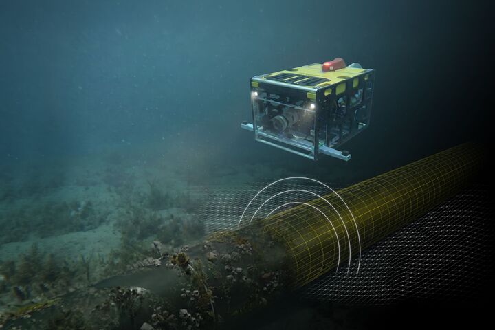
River crossing in California. Together with PG&E, EMPIT inspected parallel pipelines at a river crossing by boat. Bathymetric surveys had projected exposed pipe, dive inspections stayed incomplete in adverse water conditions, and ILI was not possible on one line. Where IMU data existed, pitch and azimuth from CMI were validated against it, and the strain comparison showed good agreement. The case was presented at the International Pipeline Conference (IPC) 2026 in Calgary.

CMI survey by boat at the river crossing.
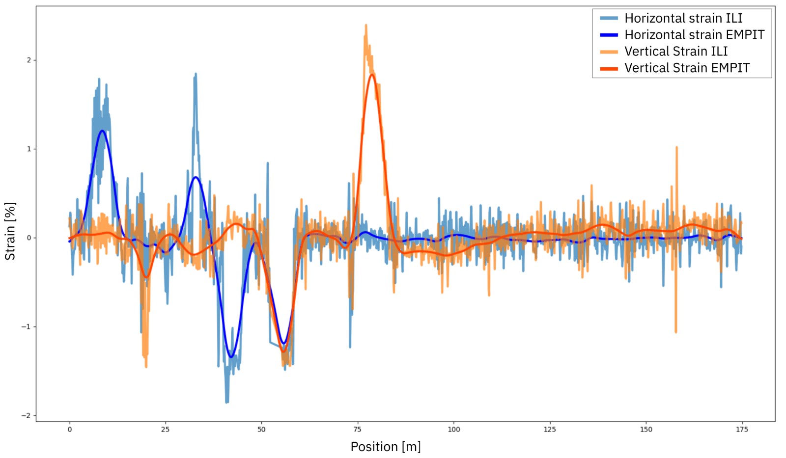
River crossing: horizontal and vertical strain from CMI (smooth lines) against ILI. Source: EMPIT, IPC 2026.
Recognized as a method. The 2023 INGAA framework lists strain computed from a surveyed pipe profile next to strain gauges and IMU as a way to determine strain demand. It also expects lower uncertainty when two methods confirm each other. An above-ground profile is therefore useful on piggable lines too, as the second method.
Bending strain is strain demand from bending. Like IMU data, it does not show uniform tension or compression along the pipe, and construction bends have to be separated from ground movement. What the girth welds can take is a separate assessment.
Geohazard sites rarely have one problem. Where a slope moves or a river erodes its bed, cover is lost and coatings are damaged. The same CMI survey delivers:
Bending strain is the stretch of the pipe wall on the outside of a bend, in percent. It equals the pipe diameter divided by twice the bend radius. Ground movement such as a landslide bends a pipeline after construction and adds strain the design did not plan for.
Yes. CMI maps the pipe centerline in 3D from above ground and derives horizontal and vertical bending strain from its curvature. No pig, launcher or excavation is needed, and the pipeline stays in service.
On a Swissgas pipeline, three in-line inspection runs reported 0.20%, 0.26% and 0.24% vertical bending strain in one area. CMI measured 0.25%. The comparison is published in the Pipeline Technology Journal 3/2025.
Send us the route of one section on a slope or at a river crossing. We will tell you what a CMI survey can deliver there.
Sources
Read more